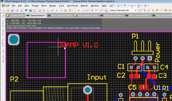

To increase the speed of increasing or decreasing the arcs, hold the shift key down while using the “.” and “,” keys.

The size of the arc is given to you in text at the bottom of the design session window, and you can increase or decrease the size of the arc by holding down the “.” or “,” keys. You can use the Shift > Spacebar to cycle through the five corner modes, and you can also use the spacebar by itself to toggle the direction of the corners. Using the Modify feature to create a notch in the board outlineĪltium Designerprovides you with five corner modes while creating the shapes for board outlines and cutouts. On the right side is the finished modification of the board outline with the notch. In the left picture below,themodify command allows us to specify a notch in the board outline. Using the Redefine feature to create a new board outlineĪnother useful function is changingyour existing board outline with the modify command. On the bottom half of the picture, you can see the results of when we completed the new board outline. It will allow you to draw a new board outline by clicking your mouse to place the vertices of the board outline as you can see in the top of the picture below. If the existing board outline is not going to be useful at all to you, you can use the redefine command to create a new board outline from scratch.

First, let’s look at redefining the board outline. You can redefine, edit, modify, and move it. The design menu gives you a number of options for working on your board outline. The Design pulldown menu in Altium Designer When you are finished moving the board corners and edges to their desired locations, click outside the board outline to exit the edit mode. Once we click there, that will become the new location for that corner of the board outline. You can see in the picture above that we have grabbed the upper left editing handle of the Test board outline and pulled it down and to the right. Moving a corner while editing the board outline You can change the size and shape of the board outline by grabbing one of those handles and dragging it to a new location, or by grabbing an edge of the board and dragging it. Once you are in this command you will see the editing handles around the board outline. To do this, you will use the Design > Edit Board Shape pulldown menu command. Now you are ready to change PCB board size of the existing board outline in your design session. Setting the board planning mode in Altium Designer In our Test design, entering the board planning mode turns the board outline to a green color which you can also see below. You can enter the board planning mode by using the menu selection as shown in the picture below, or by clicking in the board and pressing “1”.


 0 kommentar(er)
